


10 minutes, 23 seconds read
Published on Jul 12, 2018
Updated on Nov 14, 2019
Create superior customer experiences to enhance competitive advantage.
Go from zero to breakthrough with scalable, future-proof solutions.
Harness deep tech for smarter solutions and maximum impact.
Accelerate value delivery with powerful pre-built digital tools.
Help businesses connect with an internet first generation.
Test the smarter way: where precision meets efficiency.
Unlock real-time and personalized customer journeys for mobile first generation.
Turn data into decisive action with scalable AI infrastructure.
Design agile digital foundations that scale with tomorrow's business needs.
Build new-age architecture for maximum efficiency and hyper-growth.
Fine-tune your cloud infrastructure for peak performance.
Automated compliance and control for global regulations.

All
Customer Experience
Mantra
Application Development
Insurtech
Digital Health
Insurance
Deep-Tech
AgriTech(1)
Augmented Reality(21)
Clean Tech(9)
Customer Journey(17)
Design(45)
Solar Industry(8)
User Experience(68)
Edtech(10)
Events(34)
HR Tech(3)
Interviews(10)
Life@mantra(11)
Logistics(6)
Manufacturing(5)
Strategy(18)
Testing(9)
Android(48)
Backend(32)
Dev Ops(11)
Enterprise Solution(33)
Technology Modernization(9)
Frontend(29)
iOS(43)
Javascript(15)
AI in Insurance(41)
Insurtech(67)
Product Innovation(59)
Solutions(22)
E-health(12)
HealthTech(25)
mHealth(5)
Telehealth Care(4)
Telemedicine(5)
Artificial Intelligence(154)
Bitcoin(8)
Blockchain(19)
Cognitive Computing(8)
Computer Vision(8)
Data Science(24)
FinTech(51)
Banking(7)
Intelligent Automation(27)
Machine Learning(48)
Natural Language Processing(14)
I have been writing a large variety of computer programs since a long time, but there was this question, the answer to which was elusive for a long time.
My fascination started with a smart wall clock (http://ingrein.com) that I thought was a very cool gadget to have at home. I wanted to build something like that on my own, but didn’t had know how. So I started on a journey to learn embedded systems and their functioning.
I moved from Arduino to Raspberry Pi, and then to RedBear Duo, learning new things at every step. And then finally came BeagleBone Black. I had always wondered how Linux kernel works, is it something that I can compile on my own, and execute? I have been trying to solve this problem for so long and I want to thank Pavel Botev for helping me out on this.
BeagleBone Black (BBB) comes with a TI processor AM3358. So in order to build Linux kernel for this board, you will need TI SDK that can be downloaded at http://www.ti.com/tool/PROCESSOR-SDK-AM335X.
You will need to download and install the binary (Linux Processor SDK for AM335x) from the link above. Help on installation is available here — http://software-dl.ti.com/processor-sdk-linux/esd/docs/latest/linux/index.html.
There are two distinct steps in the installation of SDK. First setting the execute permission on the SDK bin file, and second to execute it.
$ chmod +x ./ti-processor-sdk-linux-[platformName]-evm-xx.xx.xx.xx-Linux-x86-Install.bin$ ./ti-processor-sdk-linux-[platformName]-evm-xx.xx.xx.xx-Linux-x86-Install.bin
Once the TI Processor SDK is installed, you will find the following file structure in the install location.
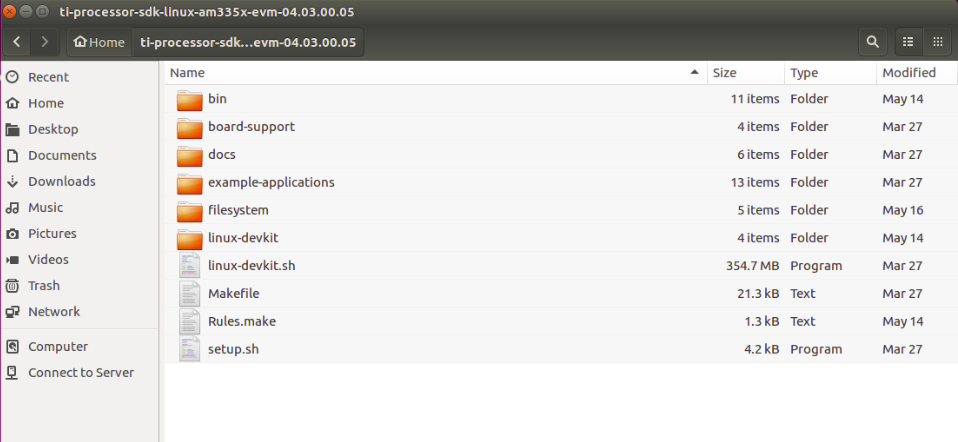
This SDK contains both the Linux kernel, and the Root File System, and other cross compile binaries (compiler) to compile the kernel. Assuming ti-processor-sdk-home is the SDK install location, you will find the kernel files at
<ti-processor-sdk-home>/board-support/linux-4.9.69+gitAUTOINC+xxxx (The exact version may vary depending on the version of the processor SDK)
and the RFS at
<ti-processor-sdk-home>/filesystem
You can copy these to separate folders so you always have the original SDK copy. In case anything goes wrong, and you want to restart from beginning, you have the kernel, and RFS that you can copy again from the Processor SDK.
Lets assume you copied the kernel files to location ~/linux-4.9.69, and changed your current directory to where you copied the kernel.
$ cd ~/linux-4.9.69
Before you compile the kernel, we must prepare the kernel by telling what is the board that we want to compile the kernel for? In other words you define the configuration by selecting appropriate defconfig file. For BeagleBone Black, we need to use “tisdk_am335x-evm_defconfig”. All config files are present in arch/arm/configs folder.
Command for setting this configuration is
$ make ARCH=arm CROSS_COMPILE=<ti-processor-sdk-home>/linux-devkit/sysroots/x86_64-arago-linux/usr/bin/arm-linux-gnueabihf- tisdk_am335x-evm_defconfig
Please note the space between “arm-linux-gnueabihf-” and “tisdk_am335x-evm_defconfig” in the above command.
You may want to configure your linux distribution further by informing the compiler what all files/modules should be included for compilation. “menuconfig” is the target for this configuration, and the full command to run menuconfig is below.
But before you run menuconfig target, there is one more step. We need to tell menuconfig what all options should be shown in menuconfig, and how. Though most of the settings are good by default, we need to do one change in the kernel
$ vi ti-processor-sdk-home/board-support/linux-4.9.69+gitAUTOINC+xxxx/sound/soc/codecs/Kconfig
Find line
config SND_SOC_PCM5102A
       tristate
And replace it with
config SND_SOC_PCM5102A
       tristate "Texas Instruments PCM5102a Dummy Codec Driver"
The above line “Texas Instruments PCM5102a Dummy Codec Driver” helps you identify the codec in the menuconfig stage.
Finally run “menuconfig” target with the following command.
$ make ARCH=arm CROSS_COMPILE=<ti-processor-sdk-home>/linux-devkit/sysroots/x86_64-arago-linux/usr/bin/arm-linux-gnueabihf- menuconfig
Please note again that menuconfig is the target name, and the value for CROSS_COMPILE flag ends with a hyphen as “arm-linux-gnueabihf-”. There should be space between “arm-linux-gnueabihf-” and “menuconfig”.
Running “menuconfig” target opens up a menu through which you can select which modules you would like to be compiled in-line, i.e. along with rest of kernel code, and which ones to be compiled, and included as modules. Mark module PCM5102a to be inline compiled along with other kernel files.
Now in order to compile the Linux Kernel, you have the kernel source files, and the cross compile binaries needed to compile the source. Compile the kernel using
$ cd ~/linux-4.9.69
$ make ARCH=arm CROSS_COMPILE=<ti-processor-sdk-home>/linux-devkit/sysroots/x86_64-arago-linux/usr/bin/arm-linux-gnueabihf- uImage LOADADDR=0x80008000 -j4
The above command compiles the kernel and keeps the image at arch/arm/boot/uImage. You can copy this image and flash it to the board, or transfer it via tftp. I shall explain the process of using tftp later.
The device tree source files are present in linux-4.9.69/arch/arm/boot/dts folder in the kernel. The device tree is the code that tells the kernel what all hardware is available on the board, and how is it configured.
Before we compile the device tree, we need to know which device tree we will be using. As this experiment is about BBB, it is obvious that BeagleBone’s device tree should be used. It is present as linux-4.9.69/arch/arm/boot/dts/am335x-boneblack.dts.
But we want to interface an I2S mems microphone (SPH0645LM4H, https://www.adafruit.com/product/3421) with BBB, we will need to tell the device tree of its presence, and its configuration. We will include all microphone related configuration in a separate DTSI file (include file, which can be included in the parent device tree source).
$ vi am335x-boneblack-pcm5102a.dtsi
The content of this include file is as below
/*
* Copyright(C) 2016 Texas Instruments Incorporated- http://www.ti.com/
*
* This program is free software; you can redistribute it and/or modify
* it under the terms of the GNU General Public License version 2 as
* published by the Free Software Foundation.
*/
&am33xx_pinmux {
 mcasp1_pins: mcasp1_pins{
  pinctrl-single,pins = <
   /* sink must enable receivers */
   AM33XX_IOPAD(0x9a0, PIN_INPUT_PULLDOWN | MUX_MODE3) /* P9_42 mcasp1_aclkx - bit clock */
   AM33XX_IOPAD(0x9a4, PIN_INPUT_PULLDOWN | MUX_MODE3) /* P9_27 mcasp1_fsx - frame sync */
   AM33XX_IOPAD(0x9a8, PIN_INPUT_PULLDOWN | MUX_MODE3) /* P9_41 mcasp1_axr0 - i2s input */
  >;
 };
};
&mcasp1 {
 #sound-dai-cells = <0>;
 pinctrl-names = "default";
 pinctrl-0 = <&mcasp1_pins>;
 status = "okay";
 op-mode = <0>; /* MCASP_IIS_MODE */
 tdm-slots = <2>;
 num-serializer = <4>;
 serial-dir = < /* 1 TX 2 RX 0 unused */
  2 1 0 0
 >;
 rx-num-evt = <32>;
 tx-num-evt = <32>;
};
/ {
 pcm5102a: pcm5102a {
  #sound-dai-cells = <0>;
  compatible = "ti,pcm5102a";
  status = "okay";
 };
clk_mcasp1_fixed: clk_mcasp1_fixed {
  #clock-cells = <0>;
  compatible = "fixed-clock";
  clock-frequency = <24576000>;
 };
clk_mcasp1: clk_mcasp1 {
  #clock-cells = <0>;
  compatible = "gpio-gate-clock";
  clocks = <&clk_mcasp1_fixed>;
  enable-gpios = <&gpio1 27 0>; /* BeagleBone Black Clk enable on GPIO1_27 */
 };
sound1:sound@1 {
  compatible = "simple-audio-card";
  simple-audio-card,name = "PCM5102a";
  simple-audio-card,format = "i2s";
  simple-audio-card,bitclock-master = <&sound1_master>;
  simple-audio-card,frame-master = <&sound1_master>;
  simple-audio-card,bitclock-inversion;
sound1_master: simple-audio-card,cpu {
   sound-dai = <&mcasp1>;
   system-clock-direction = "out";
   system-clock-frequency = <24576000>;
   clocks = <&clk_mcasp1>;
  };

  simple-audio-card,codec{
   sound-dai = <&pcm5102a>;
   #sound-dai-cells = <0>;
  };
 };
};
Now we need to include this “am335x-boneblack-pcm5102a.dtsi” file in “am335x-boneblack.dts”. Just add this line at the end of “am335x-boneblack.dts”.
#include "am335x-boneblack-pcm5102a.dtsi"
The device tree can be compiled using
$ cd ~/linux-4.9.69
$ make ARCH=arm CROSS_COMPILE=<ti-processor-sdk-home>/linux-devkit/sysroots/x86_64-arago-linux/usr/bin/arm-linux-gnueabihf- dtbs
The above command will result in a device tree binary within arch/arm/boot/dts/ folder. The file is named am335x-boneblack.dtb
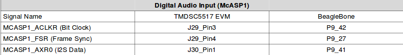
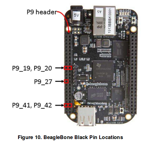
Lets now talk about how the MEMS microphone should be wired up. We can focus only on the BeagleBone column of the image below.
Booting the BBB
Now that all configuration is setup, we should march ahead with booting of your BBB. But wait, what you have is a kernel image (uImage) and a device tree binary (am335x-boneblack.dtb). But how do we send these to our BBB?
Instead of flashing the kernel, device tree, and the RFS to an SD card, and then putting the SD card to BBB, we will makes these available to BBB directly from the host computer via TFTP (for uImage, & DTB) and NFS (for RFS).
TFTP
We will use TFTP to provide the kernel image, and DTB to the BBB. Go ahead and install TFTP on your host computer.
sudo apt-get install tftpd-hpa
Now let us configure TFTP and tell it the location of the files we need to transfer to the BBB. TFTP configuration files is present as/etc/default/tftpd-hpa. Example configuration is below
# /etc/default/tftpd-hpa
TFTP_USERNAME="tftp"
TFTP_DIRECTORY="/home/parag/linux-4.9.69/arch/arm/boot"
TFTP_ADDRESS=":69"
TFTP_OPTIONS="--secure --create"
The above configuration makes “/home/parag/linux-4.9.69/arch/arm/boot” as TFTP_DIRECTORY, which is the default directory where tftp looks for files that it can transfer. TFTP is not known to work very well with nested directories, so we must ensure that both files (uImage, and DTB) are available in this directory.
As uImage is created in above directory itself, so its not a problem, and TFTP can easily transfer it. However DTB is formed within boot/dts. We can create a symbolic link in the boot itself, and make it point to DTB file present in dts directory to make it work.
ln -s dts/am335x-boneblack.dtb am335x-boneblack.dtb
Sharing RFS (Root File System) over NFS (Network File System)
RFS or the Root File System contains binaries that you typically see in any linux distribution. RFS is made available by TI SDK as indicated early in this article. You can just copy those files from SDK, and keep it at a desired location from where you can share them over network via NFS.
NFS server can be installed on ubuntu host computer with the following commands
sudo apt-get update
sudo apt-get install nfs-kernel-server
Once NFS is installed, you can proceed with its configuration. Edit /etc/exports
sudo vim /etc/exports
You can configure the above file with the following setting
/home/parag/bbone/rootfs *(rw,sync,no_root_squash,no_subtree_check)
Note, I have kept my RFS files in /home/parag/bbone/rootfs. You change this setting depending upon where you have copied the RFS files to.
Finally, booting the BBB!!
After all this hard work, its time to see the magic. Connect BBB with LAN cable, and connect it to the same network as your host computer.
Power up the BBB. Assuming you have minicom or any other serial monitor set up, you should be able to see the uboot logs. Immediately press space key so the bootloader (uboot) does not boot the kernel available in BBB, but stops for further commands. Type commands as below to help BBB connect to the network.
>setenv autoload no
>setenv serverip 192.168.1.101
>setenv gatewayip 192.168.1.1
>dhcp
I have used 192.168.1.101 as IP of my host computer, and 192.168.1.1 as the gateway. You will need to choose these according to your setup. Finally dhcp command will help BBB to be allocated an IP address from your router.
If everything goes on file, you will see output from BBB uboot that an IP has been assigned. Next command as follows
>tftpboot 0x80F80000 am335x-boneblack.dtb && tftpboot 0x80007FC0 uImage
The above command instructs u-boot to download the device tree image from the serverip instructed earlier, and copy the same to address 0x80F80000 in RAM. Kernel uImage is also downloaded from the host serverip and copied to 0x80007FC0.
Boot, finally!!
The last two commands to start the boot process are as below
>setenv bootargs console=ttyO0,115200n8 noinitrd rw ip=dhcp root=/dev/nfs nfsroot=192.168.1.101:/home/parag/bbone/rootfs nfsrootdebug earlyprintk>bootm 0x80007FC0 - 0x80F80000
The first command above sets up the bootargs. Change the setting as per your environment. The last command starts the boot process.
Soon you should see the kernel boot to complete, and a login prompt to appear. Login using root as user. No password should be needed.
Unexpected Signal on P9_41 :(
Now you will find (on your oscilloscope) that the moment you boot the kernel, you start getting a signal (square wave) on the data pin (P9–41). Ideally there should be no signal on the data pin till you start recording using the “arecord” command.
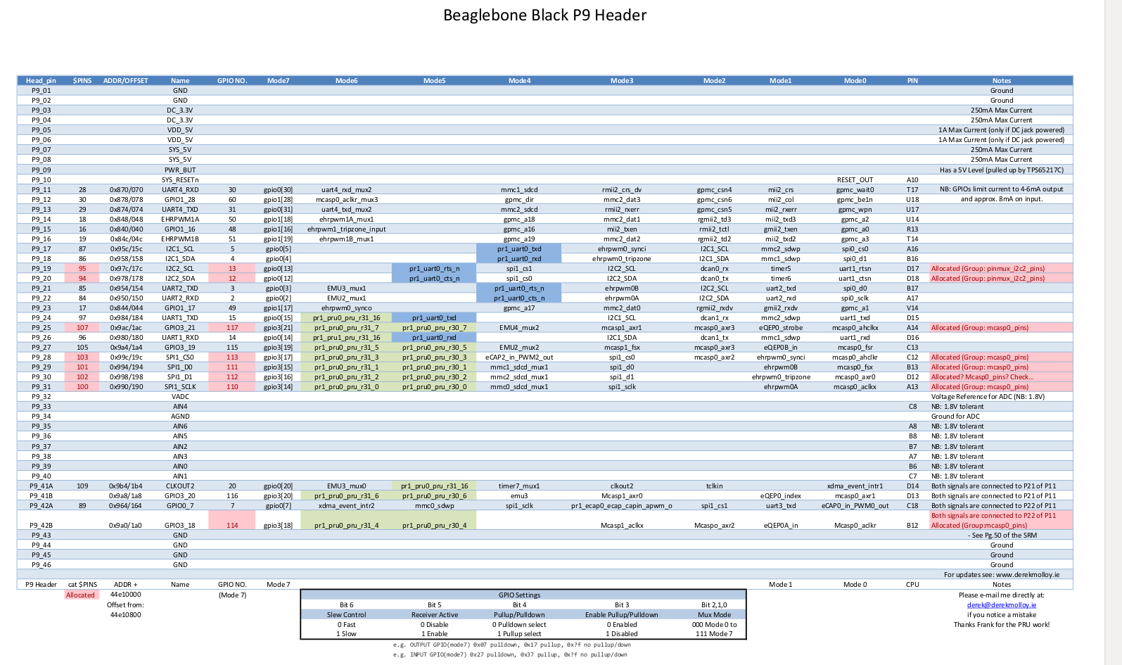
You would notice there is pinmux settings for clkout2 (mode 3) for Pin P9_41A which is the data pin. We need to disable this setting so that data pin receives only the data we record from microphone, and not from any other source.
The above observation is because of a configuration in the am335x-bone-common.dtsi (a file included in am335x-boneblack.dts).
&am335x_pinmux{
pinctrl-names = "default"
pinctrl-0 = <&clkout2_pins>
It is this line `pinctrl-0 = <&clkout2_pins>` that causes the signals on data pin. We need to comment this out like below.
&am335x_pinmux{
pinctrl-names = "default"
/*pinctrl-0 = <&clkout2_pins>*/
After this above change, we need to build again the device tree, and reboot the kernel. The data pin should not have any signal now till we start recording with the command.
$ arecord -Dhw:1,0 -f S32_LE -t wav -c 1 -d 60 -vvv /tmp/audio.wav
The above command shall start recording mono sound (single channel) at /tmp/audio.wav. The above command’s -D flag (-Dhw:1,0) assumes your PCM5102a sound card is listed at index 1. This index can be confirmed by listing down all cards and seeing the output of the command below
$ arecord -l

If you found this article helpful, let me know in the comment section below.
Knowledge thats worth delivered in your inbox
Smart Manufacturing starts with real-time visibility.
Manufacturing companies today generate data by the second through sensors, machines, ERP systems, and MES platforms. But without real-time insights, even the most advanced production lines are essentially flying blind.
Manufacturers are implementing real-time dashboards that serve as control towers for their daily operations, enabling them to shift from reactive to proactive decision-making. These tools are essential to the evolution of Smart Manufacturing, where connected systems, automation, and intelligent analytics come together to drive measurable impact.
Data is available, but what’s missing is timely action.
For many plant leaders and COOs, one challenge persists: operational data is dispersed throughout systems, delayed, or hidden in spreadsheets. And this delay turns into a liability.
Real-time dashboards help uncover critical answers:
By converting raw inputs into real-time manufacturing analytics, dashboards make operational intelligence accessible to operators, supervisors, and leadership alike, enabling teams to anticipate problems rather than react to them.
Line performance and downtime trends
Track OEE in real time and identify underperforming lines.
Predictive maintenance alerts
Utilize historical and sensor data to identify potential part failures in advance.
Inventory heat maps & reorder thresholds
Anticipate stockouts or overstocks based on dynamic reorder points.
Quality metrics linked to operator actions
Isolate shifts or procedures correlated with spikes in defects or rework.
These insights allow production teams to drive day-to-day operations in line with Smart Manufacturing principles.
Role-based dashboards
Dashboards can be configured for machine operators, shift supervisors, and plant managers, each with a tailored view of KPIs.
Embedded alerts and nudges
Real-time prompts, like “Line 4 below efficiency threshold for 15+ minutes,” reduce response times and minimize disruptions.
Cross-functional drill-downs
Teams can identify root causes more quickly because users can move from plant-wide overviews to detailed machine-level data in seconds.
Data lakehouse integration
Unified access to ERP, MES, IoT sensor, and QA systems—ensuring reliable and timely manufacturing analytics.
ETL pipelines
Real-time data ingestion from high-frequency sources with minimal latency.
Visualization tools
Custom builds using Power BI, or customized solutions designed for frontline usability and operational impact.
Mantra Labs partnered with a North American die-casting manufacturer to unify its operational data into a real-time dashboard. Fragmented data, manual reporting, delayed pricing decisions, and inconsistent data quality hindered operational efficiency and strategic decision-making.
As this case shows, real-time dashboards are not just operational tools—they’re strategic enablers.
(Learn More: Powering the Future of Metal Manufacturing with Data Engineering)
| Aspect | What You Should Know |
| 1. Why Static Reports Fall Short | Delayed insights after issues occur Disconnected systems (ERP, MES, sensors) No real-time alerts or embedded decision logic |
| 2. What Real-Time Dashboards Enable | Track OEE and downtime in real-time Predictive maintenance using sensor data Dynamic inventory heat maps Quality linked to operators |
| 3. Dashboards That Drive Action | Role-based views (operator to CEO) Embedded alerts like “Line 4 down for 15+ mins” Drilldowns from plant-level to machine-level |
| 4. What Powers These Dashboards | Unified Data Lakehouse (ERP + IoT + MES) Real-time ETL pipelines Power BI or custom dashboards built for frontline usability |
Smart Manufacturing dashboards aren’t just analytics tools—they’re productivity engines. Dashboards that deliver real-time insight empower frontline teams to make faster, better decisions—whether it’s adjusting production schedules, triggering preventive maintenance, or responding to inventory fluctuations.
Explore how Mantra Labs can help you unlock operations intelligence that’s actually usable.
Knowledge thats worth delivered in your inbox


Our Sales Team will be in touch with you shortly.

Hello Stranger! Please fill in a few details,and you’ll receive a link to this case study.
 We have mailed you this case study.
Thanks for subscribing.
